 Bob Tilden
In 2011, my son and I completed an aluminum foundry. Built entirely from salvage yard scrap, we created a system capable of melting down old transmission housings and turning them into useful, new parts.
THE FOUNDRY
The pictures below show the construction and initial learning phases of the foundry.
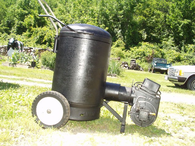
The furnace was built from a 30 gallon propane tank that was shortened up. the interior is lined with a commercial refractory cement; several homebrew refractories were tried and found to be more trouble than the money they saved. The furnace is fired with a conventional oil burner gun.
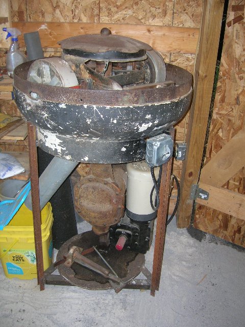
The muller. Nobody does serious casting without a muller to mix or moisten their sand. I cannot imagine working without it.
The muller body is made from the top of a 125 gallon propane tank, cut loose and inverted as a bowl. A quarter inch plate steel was welded in to make a flat floor for the squisher wheels to run on. The squisher wheels are machined from discarded concrete- grinder wheels and loaded with two barbell weights. The rotating assembly… the wheels and their mounting frame… weigh about 100 lbs.
Muller Construction
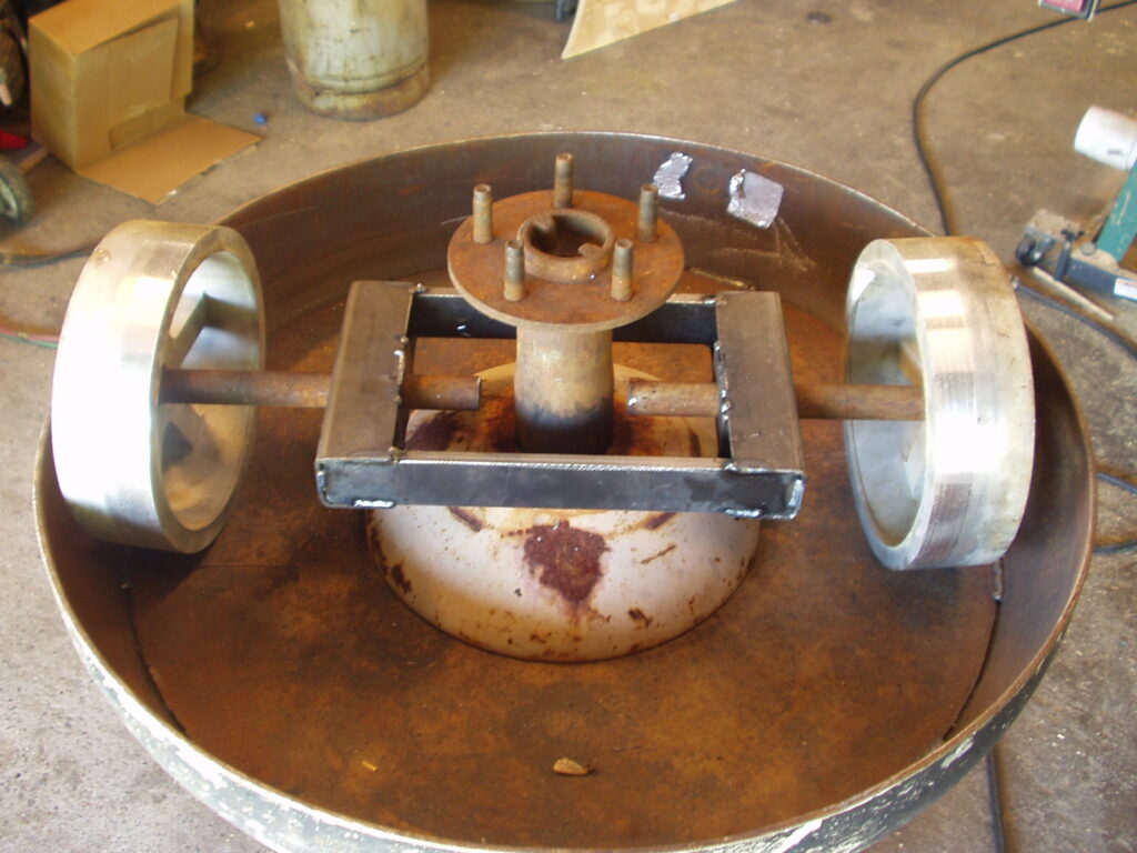
The muller framework and drive train have been built at this point and this photo is a mock- up of the muller bowl. The axle- end of the rear- end assembly protrudes through the bowl bottom and the steel plate floor that the wheels run against. The dome at the center of the muller floor is the top of a small propane tank… It fills an area that would otherwise collect “dead” sand.
Note that the wheels ride on axles which carry through the center of the muller via a box section. An automotive wheel rim was cut and formed so that when installed on the axle hub, a slot aligned with each axle. The axles, riding in the slots are turned by the rotating wheel rim, but are free to ride up and down as needed. The wheels were weighted with barbell weights, and the hollow tubes of the carry- through were filled with lead. The sand is “squished” by the weight of the wheels, axles, and carry-through.
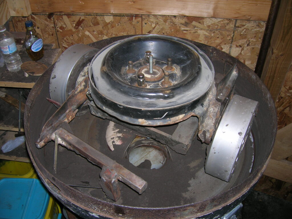
In this photo, the wheels and carry-through are still visible, but are covered by the wheel rim that drives them. It is difficult to see clearly, but the axles protrude through slots in the wheel rim, and that the plows are attached to arms that project from the whel rim. Near the center of the muller bowl is the sand exit. In use, this area is blocked by a small cover during operation, and the cover is removed to dump the sand through the hole, down a pipe, and into a 5 gallon pail. Yes, a dump chute on the outside perimeter of the muller bowl would have worked better!
This muller is happy working loads of about 5 gallons… 50 lbs?
The machine was originally powered with a 3- phase 3HP motor from the scrap yard, but we determined that a 1HP single phase motor would work just as well and not require us to be running back and forth to the phase converter switch. The motor drives a right angle gear reduction which chain-drives a small pickup truck rear- end. One axle was cut from it, and the other axle protrudes through the bottom of the bowl and the floor plate. A suitably butchered tire rim is bolted to the end of the axle and it slips over the squisher wheel assembly. It turns about 25 RPM and pulls a pair of plows behind it; one plow scrapes the sand from the outside in, and the other moves the sand from the inside out. Capping the unit is a cultivating disk and part of a “finial” from a wrought iron fence rail. God bless scrap dealers who let you go “shopping!”
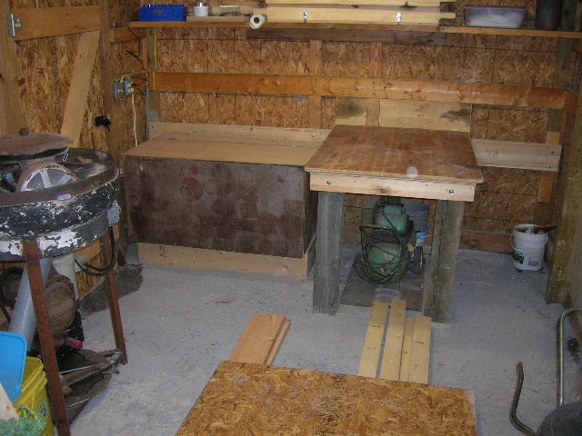
The foundry interior… which we have not used yet! We spent four weekends learning how to make a “perfect” part, and for each of those weekends the casting operation took over my workshop. Sand got everywhere; it was OK as a temporary fix, but unsustainable as a permanent function.
To the left is the muller, then the insulated sand box which can be heated to keep the sand from freezing, and then the “pounding table” for ramming up flasks. A wheezy old air compressor lives under the bench. The boards on the sandy floor are for a 10 X 10 pavilion roof for the melting and pouring operations, although there is also provision to do that inside when the weather is really poor.
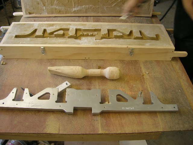
The back of the pattern faces the camera after it has been removed from the cope and drag. This was our first attempt at mold- making… note that the sand has never been used. Our sand is a fine “fracking” sand that comes to the area by the trainload and moves out by the truckload… Some is always spilled, and my son got a ton of it, bucket by bucket, from between the rails. We mix it with bentonite. The pattern is a wheel truck for a 1/12 scale DD40 diesel locomotive. The need for this part has driven this whole foundry project.
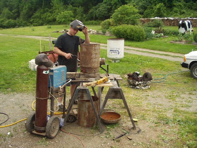
June 2010, the start of the project. Brian is welding on the furnace body; below the table is the excluded length of the tank, and the top which was reattached with a swivel. In the near background is the propane tank top (black, full of junk) that became the muller bowl. The remainder of the tank became a fan-tastic burn barrel. Further in the background is my “tin cow”, made from a 275 gallon oil tank, a milk can, and some other scrap.
The welding cart is still another story. It rides on a set of Planet Junor” rototiller wheels and was specifically designed to maneuver the welder and its large gas tank through a cluttered shop.
I also built a “breaking furnace” which melts transmission cases, engine heads, etc into ingots to feed the casting furnace. It looks crude but runs very well. Click here to watch a You Tube video of it at work.
Here are some later photos from the project:
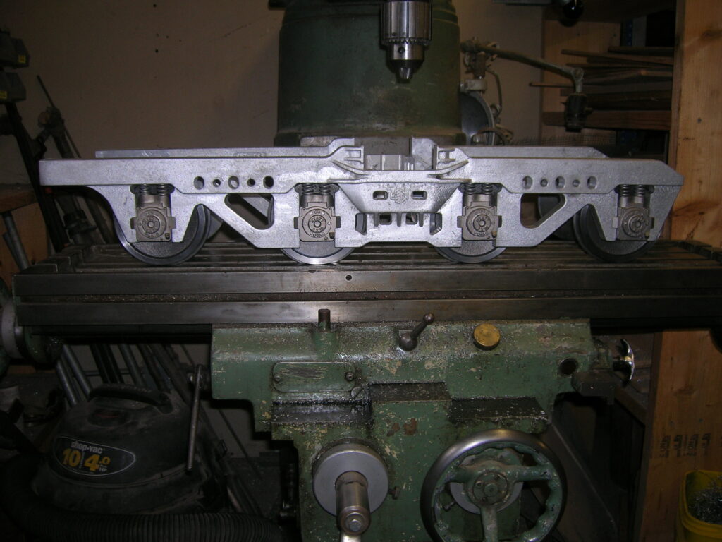
Our foundry exists because of a need for this part..
Pictured above is a one- inch- per- foot scale mockup of an EMD DD-40 wheel truck. The biggest part is the side frame assembly which carries the four axles. Initially Brian planned to machine each of the four side frames from aluminum billet stock, but after completing one part, it was apparent that he would need to start with bigger pieces of billet, that modifications would be nearly impossible after machining, and that goofs would be very expensive. It was also apparent that casting the part- and all the other parts what would be needed to make a locomotive- would be the best thing to do. The part which had already been machined was turned into a pattern by sculpting draft onto the part using epoxy putty. The part is now in its fourth revision, with the addition of several cosmetic and structural details.
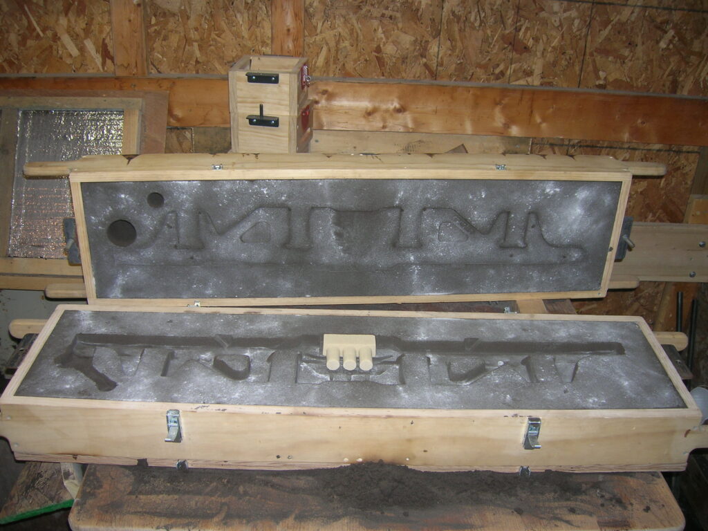
Quite a change from the ready-to-close mold pictured on the other foundry page. The sand is jet black from usage and a core is now used to rough-out the spring mounts. Prior to using the core, there seemed no way to eliminate shrinkage from the thick center section. Many less noticeable details have been added, especially the small bosses to mount the actuation linkages.
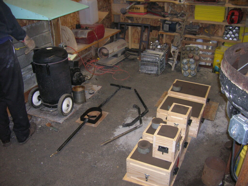
Also shown in this picture is part of the muller on the right, stacks and baskets of ingots in the center, and the furnace on the left. The furnace has rubber wheels which never get hot enough to be bothered, and it is located next to a wall which lives happily behind a shielding of stainless steel and concrete board. Home-made crucible tools are on the floor. Less apparent is the blower mounted under the green hood above the furnace. The hood swings up and out-of-the-way when it is crucible time, but otherwise it funnels the heat, smoke, and fumes outside through a salvaged furnace blower. We are pouring inside because there is a fresh foot of snow on the ground and the chill factor is in the single digits.
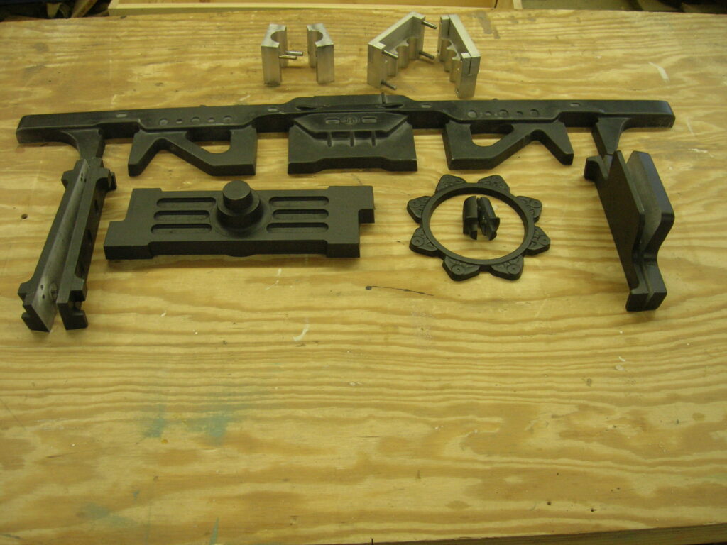
Currently, in March 2011, these are the patterns in use. At the top is the side frame pattern, and below it, from left to right The 2-part pattern for the front and middle crossmembers, the bolster which connects the truck assembly to the locomotive chassis, a ring of brake shoes with a two-part brake cylinder pattern in the middle, and a two-part pattern for the rear crossmember. At the top of the picture are core molds for the bolster center pin and the side frame spring mounts.


Add comment